Data Communication Overview
A system of interconnected computers and computerized peripherals such as printers is called computer network. This interconnection among computers facilitates information sharing among them. Computers may connect to each other by either wired or wireless media.Classification of Computer Networks
Computer networks are classified based on various factors.They includes:- Geographical span
- Inter-connectivity
- Administration
- Architecture
Geographical Span
Geographically a network can be seen in one of the following categories:- It may be spanned across your table, among Bluetooth enabled devices,. Ranging not more than few meters.
- It may be spanned across a whole building, including intermediate devices to connect all floors.
- It may be spanned across a whole city.
- It may be spanned across multiple cities or provinces.
- It may be one network covering whole world.
Inter-Connectivity
Components of a network can be connected to each other differently in some fashion. By connectedness we mean either logically , physically , or both ways.- Every single device can be connected to every other device on network, making the network mesh.
- All devices can be connected to a single medium but geographically disconnected, created bus like structure.
- Each device is connected to its left and right peers only, creating linear structure.
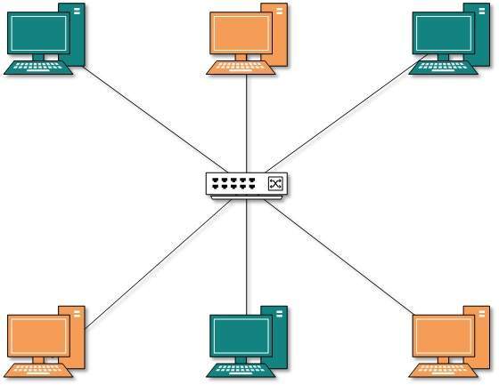
- All devices connected together with a single device, creating star like structure.
- All devices connected arbitrarily using all previous ways to connect each other, resulting in a hybrid structure.
Administration
From an administrator’s point of view, a network can be private network which belongs a single autonomous system and cannot be accessed outside its physical or logical domain.A network can be public which is accessed by all.Network Architecture
- Computer networks can be discriminated into various types such as
Client-Server,peer-to-peer or hybrid, depending upon its architecture.
- There can be one or more systems acting as Server. Other being Client, requests the Server to serve requests.Server takes and processes request on behalf of Clients.
- Two systems can be connected Point-to-Point, or in back-to-back fashion. They both reside at the same level and called peers.
- There can be hybrid network which involves network architecture of both the above types.
Network Applications
Computer systems and peripherals are connected to form a network.They provide numerou advantages:- Resource sharing such as printers and storage devices
- Exchange of information by means of e-Mails and FTP
- Information sharing by using Web or Internet
- Interaction with other users using dynamic web pages
- IP phones
- Video conferences
- Parallel computing
- Instant messaging
Computer Network Types
Generally, networks are distinguished based on their geographical span. A network can be as small as distance between your mobile phone and its Bluetooth headphone and as large as the internet itself, covering the whole geographical world,Personal Area Network
A Personal Area Network (PAN) is smallest network which is very personal to a user. This may include Bluetooth enabled devices or infra-red enabled devices. PAN has connectivity range up to 10 meters. PAN may include wireless computer keyboard and mouse, Bluetooth enabled headphones, wireless printers and TV remotes.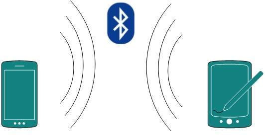 For example, Piconet is Bluetooth-enabled Personal Area Network which
may contain up to 8 devices connected together in a master-slave
fashion.
For example, Piconet is Bluetooth-enabled Personal Area Network which
may contain up to 8 devices connected together in a master-slave
fashion.Local Area Network
A computer network spanned inside a building and operated under single administrative system is generally termed as Local Area Network (LAN). Usually,LAN covers an organization’ offices, schools, colleges or universities. Number of systems connected in LAN may vary from as least as two to as much as 16 million.LAN provides a useful way of sharing the resources between end users.The resources such as printers, file servers, scanners, and internet are easily sharable among computers.
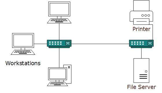 LANs are composed of inexpensive networking and routing equipment.
It may contains local servers serving file storage and other locally
shared applications. It mostly operates on private IP addresses and
does not involve heavy routing. LAN works under its own local domain
and controlled centrally.
LANs are composed of inexpensive networking and routing equipment.
It may contains local servers serving file storage and other locally
shared applications. It mostly operates on private IP addresses and
does not involve heavy routing. LAN works under its own local domain
and controlled centrally.LAN uses either Ethernet or Token-ring technology. Ethernet is most widely employed LAN technology and uses Star topology, while Token-ring is rarely seen.
LAN can be wired,wireless, or in both forms at once.
Metropolitan Area Network
The Metropolitan Area Network (MAN) generally expands throughout a city such as cable TV network. It can be in the form of Ethernet,Token-ring, ATM, or Fiber Distributed Data Interface (FDDI).Metro Ethernet is a service which is provided by ISPs. This service enables its users to expand their Local Area Networks. For example, MAN can help an organization to connect all of its offices in a city.
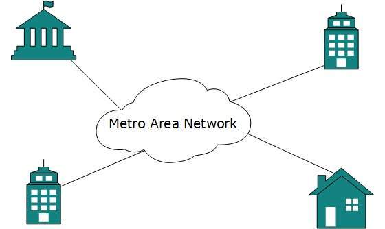 Backbone of MAN is high-capacity and high-speed fiber optics. MAN
works in between Local Area Network and Wide Area Network. MAN provides
uplink for LANs to WANs or internet.
Backbone of MAN is high-capacity and high-speed fiber optics. MAN
works in between Local Area Network and Wide Area Network. MAN provides
uplink for LANs to WANs or internet.Wide Area Network
As the name suggests,the Wide Area Network (WAN) covers a wide area which may span across provinces and even a whole country. Generally, telecommunication networks are Wide Area Network. These networks provide connectivity to MANs and LANs. Since they are equipped with very high speed backbone, WANs use very expensive network equipment.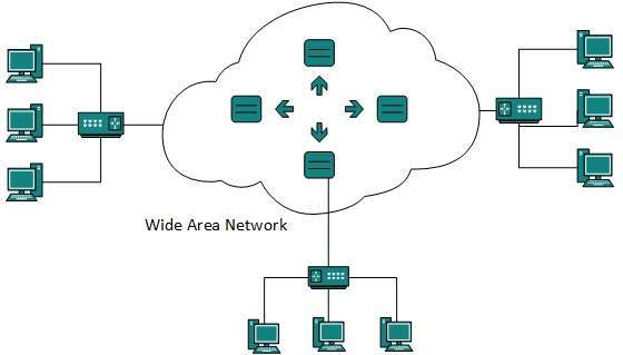 WAN may use advanced technologies such as Asynchronous Transfer Mode
(ATM), Frame Relay, and Synchronous Optical Network (SONET). WAN may be
managed by multiple administration.
WAN may use advanced technologies such as Asynchronous Transfer Mode
(ATM), Frame Relay, and Synchronous Optical Network (SONET). WAN may be
managed by multiple administration.Internetwork
A network of networks is called an internetwork, or simply the internet. It is the largest network in existence on this planet.The internet hugely connects all WANs and it can have connection to LANs and Home networks. Internet uses TCP/IP protocol suite and uses IP as its addressing protocol. Present day, Internet is widely implemented using IPv4. Because of shortage of address spaces, it is gradually migrating from IPv4 to IPv6.Internet enables its users to share and access enormous amount of information worldwide. It uses WWW, FTP, email services, audio and video streaming etc. At huge level, internet works on Client-Server model.
Internet uses very high speed backbone of fiber optics. To inter-connect various continents, fibers are laid under sea known to us as submarine communication cable.
Internet is widely deployed on World Wide Web services using HTML linked pages and is accessible by client software known as Web Browsers. When a user requests a page using some web browser located on some Web Server anywhere in the world, the Web Server responds with the proper HTML page. The communication delay is very low.
Internet is serving many proposes and is involved in many aspects of life. Some of them are:
- Web sites
- Instant Messaging
- Blogging
- Social Media
- Marketing
- Networking
- Resource Sharing
- Audio and Video Streaming
Network LAN Technologies
Let us go through various LAN technologies in brief:Ethernet
Ethernet is a widely deployed LAN technology.This technology was invented by Bob Metcalfe and D.R. Boggs in the year 1970. It was standardized in IEEE 802.3 in 1980.Ethernet shares media. Network which uses shared media has high probability of data collision. Ethernet uses Carrier Sense Multi Access/Collision Detection (CSMA/CD) technology to detect collisions. On the occurrence of collision in Ethernet, all its hosts roll back, wait for some random amount of time, and then re-transmit the data.
Ethernet connector is,network interface card equipped with 48-bits MAC address. This helps other Ethernet devices to identify and communicate with remote devices in Ethernet.
Traditional Ethernet uses 10BASE-T specifications.The number 10 depicts 10MBPS speed, BASE stands for baseband, and T stands for Thick Ethernet. 10BASE-T Ethernet provides transmission speed up to 10MBPS and uses coaxial cable or Cat-5 twisted pair cable with RJ-5 connector. Ethernet follows star topology with segment length up to 100 meters. All devices are connected to a hub/switch in a star fashion.
Fast-Ethernet
To encompass need of fast emerging software and hardware technologies, Ethernet extends itself as Fast-Ethernet. It can run on UTP, Optical Fiber, and wirelessly too. It can provide speed up to 100 MBPS. This standard is named as 100BASE-T in IEEE 803.2 using Cat-5 twisted pair cable. It uses CSMA/CD technique for wired media sharing among the Ethernet hosts and CSMA/CA (CA stands for Collision Avoidance) technique for wireless Ethernet LAN.Fast Ethernet on fiber is defined under 100BASE-FX standard which provides speed up to 100 MBPS on fiber. Ethernet over fiber can be extended up to 100 meters in half-duplex mode and can reach maximum of 2000 meters in full-duplex over multimode fibers.
Giga-Ethernet
After being introduced in 1995, Fast-Ethernet could enjoy its high speed status only for 3 years till Giga-Ethernet introduced. Giga-Ethernet provides speed up to 1000 mbits/seconds. IEEE802.3ab standardize Giga-Ethernet over UTP using Cat-5, Cat-5e and Cat-6 cables. IEEE802.3ah defines Giga-Ethernet over Fiber.Virtual LAN
LAN uses Ethernet which in turn works on shared media. Shared media in Ethernet create one single Broadcast domain and one single Collision domain. Introduction of switches to Ethernet has removed single collision domain issue and each device connected to switch works in its separate collision domain. But even Switches cannot divide a network into separate Broadcast domains.Virtual LAN is a solution to divide a single Broadcast domain into multiple Broadcast domains. Host in one VLAN cannot speak to a host in another. By default, all hosts are placed into the same VLAN.
 In this diagram, different VLANs are depicted in different color
codes. Hosts in one VLAN, even if connected on the same Switch cannot
see or speak to other hosts in different VLANs. VLAN is Layer-2
technology which works closely on Ethernet. To route packets between
two different VLANs a Layer-3 device such as Router is required.
In this diagram, different VLANs are depicted in different color
codes. Hosts in one VLAN, even if connected on the same Switch cannot
see or speak to other hosts in different VLANs. VLAN is Layer-2
technology which works closely on Ethernet. To route packets between
two different VLANs a Layer-3 device such as Router is required.Computer Network Toplogies
A Network Topology is the arrangement with which computer systems or network devices are connected to each other. Topologies may define both physical and logical aspect of the network. Both logical and physical topologies could be same or different in a same network.Point-to-Point
Point-to-point networks contains exactly two hosts such as computer, switches or routers, servers connected back to back using a single piece of cable. Often, the receiving end of one host is connected to sending end of the other and vice-versa.
Bus Topology
In case of Bus topology, all devices share single communication line or cable.Bus topology may have problem while multiple hosts sending data at the same time. Therefore, Bus topology either uses CSMA/CD technology or recognizes one host as Bus Master to solve the issue. It is one of the simple forms of networking where a failure of a device does not affect the other devices. But failure of the shared communication line can make all other devices stop functioning.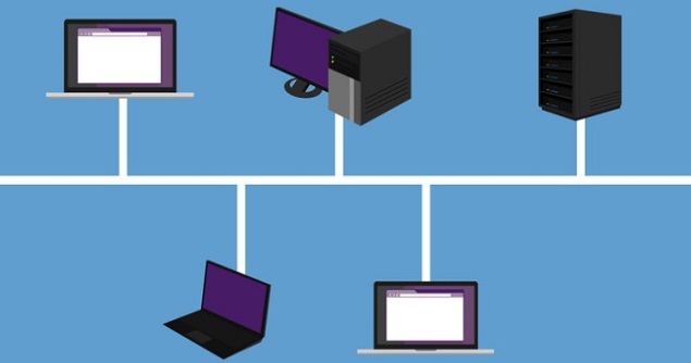 Both ends of the shared channel have line terminator. The data is
sent in only one direction and as soon as it reaches the extreme end,
the terminator removes the data from the line.
Both ends of the shared channel have line terminator. The data is
sent in only one direction and as soon as it reaches the extreme end,
the terminator removes the data from the line.Star Topology
All hosts in Star topology are connected to a central device, known as hub device, using a point-to-point connection. That is, there exists a point to point connection between hosts and hub. The hub device can be any of the following:- Layer-1 device such as hub or repeater
- Layer-2 device such as switch or bridge
- Layer-3 device such as router or gateway
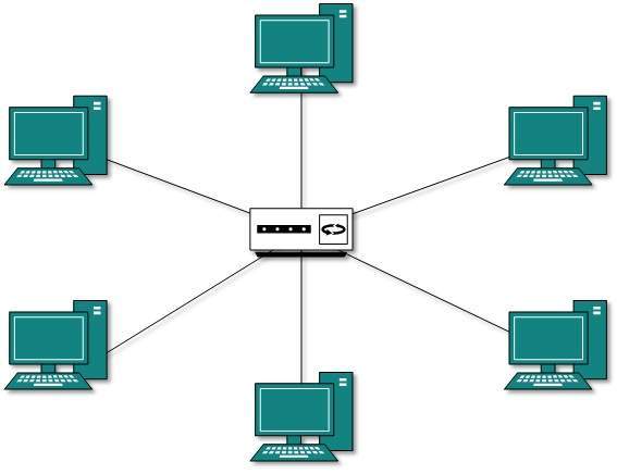 As in Bus topology, hub acts as single point of failure. If hub
fails, connectivity of all hosts to all other hosts fails. Every
communication between hosts, takes place through only the hub.Star
topology is not expensive as to connect one more host, only one cable is
required and configuration is simple.
As in Bus topology, hub acts as single point of failure. If hub
fails, connectivity of all hosts to all other hosts fails. Every
communication between hosts, takes place through only the hub.Star
topology is not expensive as to connect one more host, only one cable is
required and configuration is simple.Ring Topology
In ring topology, each host machine connects to exactly two other machines, creating a circular network structure. When one host tries to communicate or send message to a host which is not adjacent to it, the data travels through all intermediate hosts. To connect one more host in the existing structure, the administrator may need only one more extra cable.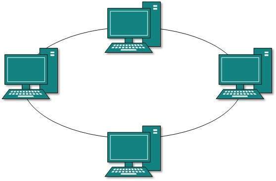 Failure of any host results in failure of the whole ring.Thus, every
connection in the ring is a point of failure. There are methods which
employ one more backup ring.
Failure of any host results in failure of the whole ring.Thus, every
connection in the ring is a point of failure. There are methods which
employ one more backup ring.Mesh Topology
In this type of topology, a host is connected to one or multiple hosts.This topology has hosts in point-to-point connection with every other host or may also have hosts which are in point-to-point connection to few hosts only.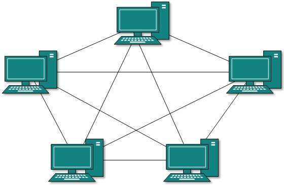 Hosts in Mesh topology also work as relay for other hosts which do
not have direct point-to-point links. Mesh technology comes into two
types:
Hosts in Mesh topology also work as relay for other hosts which do
not have direct point-to-point links. Mesh technology comes into two
types:- Full Mesh: All hosts have a point-to-point connection to every other host in the network. Thus for every new host n(n-1)/2 connections are required. It provides the most reliable network structure among all network topologies.
- Partially Mesh: Not all hosts have point-to-point connection to every other host. Hosts connect to each other in some arbitrarily fashion. This topology exists where we need to provide reliability to some hosts out of all.
Tree Topology
Also known as Hierarchical Topology, this is the most common form of network topology in use presently.This topology imitates as extended Star topology and inherits properties of bus topology.This topology divides the network in to multiple levels/layers of network. Mainly in LANs, a network is bifurcated into three types of network devices. The lowermost is access-layer where computers are attached. The middle layer is known as distribution layer, which works as mediator between upper layer and lower layer. The highest layer is known as core layer, and is central point of the network, i.e. root of the tree from which all nodes fork.
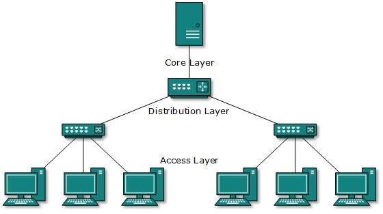 All neighboring hosts have point-to-point connection between
them.Similar to the Bus topology, if the root goes down, then the entire
network suffers even.though it is not the single point of failure.
Every connection serves as point of failure, failing of which divides
the network into unreachable segment.
All neighboring hosts have point-to-point connection between
them.Similar to the Bus topology, if the root goes down, then the entire
network suffers even.though it is not the single point of failure.
Every connection serves as point of failure, failing of which divides
the network into unreachable segment.Daisy Chain
This topology connects all the hosts in a linear fashion. Similar to Ring topology, all hosts are connected to two hosts only, except the end hosts.Means, if the end hosts in daisy chain are connected then it represents Ring topology. Each link in daisy chain topology represents single point of failure.
Every link failure splits the network into two segments.Every
intermediate host works as relay for its immediate hosts.
Each link in daisy chain topology represents single point of failure.
Every link failure splits the network into two segments.Every
intermediate host works as relay for its immediate hosts.Hybrid Topology
A network structure whose design contains more than one topology is said to be hybrid topology. Hybrid topology inherits merits and demerits of all the incorporating topologies.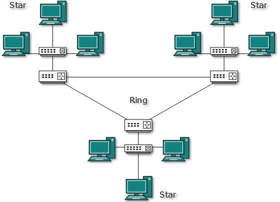 The above picture represents an arbitrarily hybrid topology. The
combining topologies may contain attributes of Star, Ring, Bus, and
Daisy-chain topologies. Most WANs are connected by means of Dual-Ring
topology and networks connected to them are mostly Star topology
networks. Internet is the best example of largest Hybrid topology
The above picture represents an arbitrarily hybrid topology. The
combining topologies may contain attributes of Star, Ring, Bus, and
Daisy-chain topologies. Most WANs are connected by means of Dual-Ring
topology and networks connected to them are mostly Star topology
networks. Internet is the best example of largest Hybrid topologyComputer Network Models
Networking engineering is a complicated task, which involves software, firmware, chip level engineering, hardware, and electric pulses. To ease network engineering, the whole networking concept is divided into multiple layers. Each layer is involved in some particular task and is independent of all other layers. But as a whole, almost all networking tasks depend on all of these layers. Layers share data between them and they depend on each other only to take input and send output.Layered Tasks
In layered architecture of Network Model, one whole network process is divided into small tasks. Each small task is then assigned to a particular layer which works dedicatedly to process the task only. Every layer does only specific work.In layered communication system, one layer of a host deals with the task done by or to be done by its peer layer at the same level on the remote host. The task is either initiated by layer at the lowest level or at the top most level. If the task is initiated by the-top most layer, it is passed on to the layer below it for further processing. The lower layer does the same thing, it processes the task and passes on to lower layer. If the task is initiated by lower most layer, then the reverse path is taken.
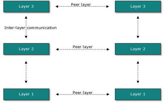 Every layer clubs together all procedures, protocols, and methods
which it requires to execute its piece of task. All layers identify
their counterparts by means of encapsulation header and tail.
Every layer clubs together all procedures, protocols, and methods
which it requires to execute its piece of task. All layers identify
their counterparts by means of encapsulation header and tail.Transmission Media
The transmission media is nothing but the physical media over which communication takes place in computer networks.Magnetic Media
One of the most convenient way to transfer data from one computer to another, even before the birth of networking, was to save it on some storage media and transfer physical from one station to another. Though it may seem old-fashion way in today’s world of high speed internet, but when the size of data is huge, the magnetic media comes into play.For example, a bank has to handle and transfer huge data of its customer, which stores a backup of it at some geographically far-away place for security reasons and to keep it from uncertain calamities. If the bank needs to store its huge backup data then its,transfer through internet is not feasible.The WAN links may not support such high speed.Even if they do; the cost too high to afford.
In these cases, data backup is stored onto magnetic tapes or magnetic discs, and then shifted physically at remote places.
Twisted Pair Cable
A twisted pair cable is made of two plastic insulated copper wires twisted together to form a single media. Out of these two wires, only one carries actual signal and another is used for ground reference. The twists between wires are helpful in reducing noise (electro-magnetic interference) and crosstalk. There are two types of twisted pair cables:
- Shielded Twisted Pair (STP) Cable
- Unshielded Twisted Pair (UTP) Cable
UTP has seven categories, each suitable for specific use. In computer networks, Cat-5, Cat-5e, and Cat-6 cables are mostly used. UTP cables are connected by RJ45 connectors.
Coaxial Cable
Coaxial cable has two wires of copper. The core wire lies in the center and it is made of solid conductor.The core is enclosed in an insulating sheath.The second wire is wrapped around over the sheath and that too in turn encased by insulator sheath.This all is covered by plastic cover.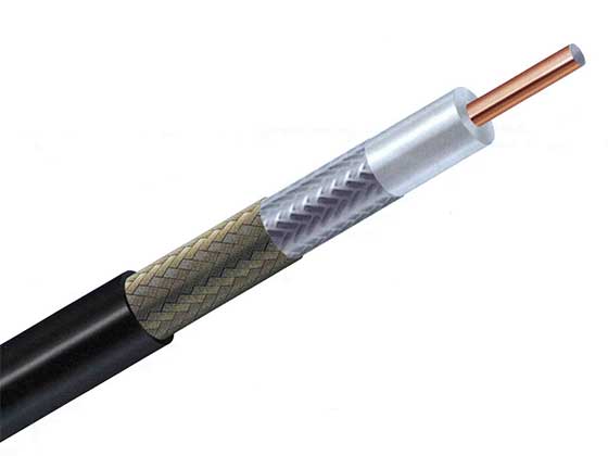 Because of its structure,the coax cable is capable of carrying high
frequency signals than that of twisted pair cable.The wrapped structure
provides it a good shield against noise and cross talk. Coaxial cables
provide high bandwidth rates of up to 450 mbps.
Because of its structure,the coax cable is capable of carrying high
frequency signals than that of twisted pair cable.The wrapped structure
provides it a good shield against noise and cross talk. Coaxial cables
provide high bandwidth rates of up to 450 mbps.There are three categories of coax cables namely, RG-59 (Cable TV), RG-58 (Thin Ethernet), and RG-11 (Thick Ethernet). RG stands for Radio Government.
Cables are connected using BNC connector and BNC-T. BNC terminator is used to terminate the wire at the far ends.
Power Lines
Power Line communication (PLC) is Layer-1 (Physical Layer) technology which uses power cables to transmit data signals.In PLC, modulated data is sent over the cables. The receiver on the other end de-modulates and interprets the data.Because power lines are widely deployed, PLC can make all powered devices controlled and monitored. PLC works in half-duplex.
There are two types of PLC:
- Narrow band PLC
- Broad band PLC
Broadband PLC provides higher data rates up to 100s of Mbps and works at higher frequencies (1.8 – 250 MHz).They cannot be as much extended as Narrowband PLC.
Fiber Optics
Fiber Optic works on the properties of light. When light ray hits at critical angle it tends to refracts at 90 degree. This property has been used in fiber optic. The core of fiber optic cable is made of high quality glass or plastic. From one end of it light is emitted, it travels through it and at the other end light detector detects light stream and converts it to electric data.Fiber Optic provides the highest mode of speed. It comes in two modes, one is single mode fiber and second is multimode fiber. Single mode fiber can carry a single ray of light whereas multimode is capable of carrying multiple beams of light.
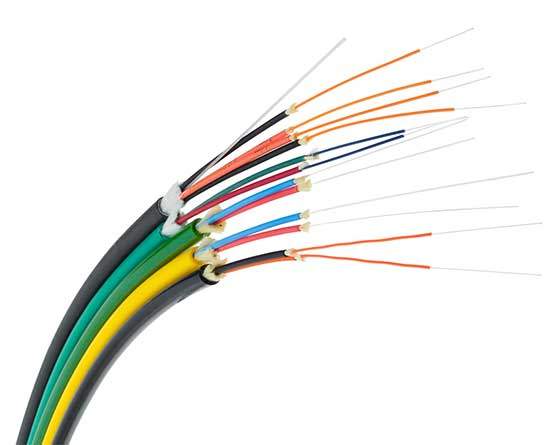 Fiber Optic also comes in unidirectional and bidirectional
capabilities. To connect and access fiber optic special type of
connectors are used. These can be Subscriber Channel (SC), Straight Tip
(ST), or MT-RJ.
Fiber Optic also comes in unidirectional and bidirectional
capabilities. To connect and access fiber optic special type of
connectors are used. These can be Subscriber Channel (SC), Straight Tip
(ST), or MT-RJ.Wireless Transmission
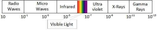
Wireless transmission is a form of unguided media. Wireless communication involves no physical link established between two or more devices, communicating wirelessly. Wireless signals are spread over in the air and are received and interpreted by appropriate antennas.When an antenna is attached to electrical circuit of a computer or wireless device, it converts the digital data into wireless signals and spread all over within its frequency range. The receptor on the other end receives these signals and converts them back to digital data.
A little part of electromagnetic spectrum can be used for wireless transmission.
Radio Transmission
Radio frequency is easier to generate and because of its large wavelength it can penetrate through walls and structures alike.Radio waves can have wavelength from 1 mm – 100,000 km and have frequency ranging from 3 Hz (Extremely Low Frequency) to 300 GHz (Extremely High Frequency). Radio frequencies are sub-divided into six bands.Radio waves at lower frequencies can travel through walls whereas higher RF can travel in straight line and bounce back.The power of low frequency waves decreases sharply as they cover long distance. High frequency radio waves have more power.
Lower frequencies such as VLF, LF, MF bands can travel on the ground up to 1000 kilometers, over the earth’s surface.
 Radio waves of high frequencies are prone to be absorbed by rain and
other obstacles. They use Ionosphere of earth atmosphere. High
frequency radio waves such as HF and VHF bands are spread upwards. When
they reach Ionosphere, they are refracted back to the earth.
Radio waves of high frequencies are prone to be absorbed by rain and
other obstacles. They use Ionosphere of earth atmosphere. High
frequency radio waves such as HF and VHF bands are spread upwards. When
they reach Ionosphere, they are refracted back to the earth. 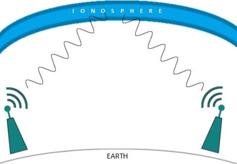
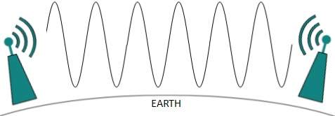
Microwave Transmission
Electromagnetic waves above 100 MHz tend to travel in a straight line and signals over them can be sent by beaming those waves towards one particular station. Because Microwaves travels in straight lines, both sender and receiver must be aligned to be strictly in line-of-sight.Microwaves can have wavelength ranging from 1 mm – 1 meter and frequency ranging from 300 MHz to 300 GHz.
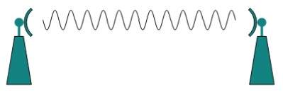 Microwave antennas concentrate the waves making a beam of it. As
shown in picture above, multiple antennas can be aligned to reach
farther. Microwaves have higher frequencies and do not penetrate wall
like obstacles.
Microwave antennas concentrate the waves making a beam of it. As
shown in picture above, multiple antennas can be aligned to reach
farther. Microwaves have higher frequencies and do not penetrate wall
like obstacles. Microwave transmission depends highly upon the weather conditions and the frequency it is using.
Infrared Transmission
Infrared wave lies in between visible light spectrum and microwaves. It has wavelength of 700-nm to 1-mm and frequency ranges from 300-GHz to 430-THz.Infrared wave is used for very short range communication purposes such as television and it’s remote. Infrared travels in a straight line hence it is directional by nature. Because of high frequency range, Infrared cannot cross wall-like obstacles.
Light Transmission
Highest most electromagnetic spectrum which can be used for data transmission is light or optical signaling. This is achieved by means of LASER.Because of frequency light uses, it tends to travel strictly in straight line.Hence the sender and receiver must be in the line-of-sight. Because laser transmission is unidirectional, at both ends of communication the laser and the photo-detector needs to be installed. Laser beam is generally 1mm wide hence it is a work of precision to align two far receptors each pointing to lasers source.
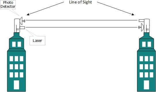 Laser works as Tx (transmitter) and photo-detectors works as Rx (receiver).
 Lasers cannot penetrate obstacles such as walls, rain, and thick fog. Additionally, laser beam is distorted by wind, atmosphere temperature, or variation in temperature in the path.
Laser is safe for data transmission as it is very difficult to tap 1mm wide laser without interrupting the communication channel.


0 comments:
Post a Comment